android 自定义View 继承View
上篇关于自定义View的介绍
接下来将会针对自定义View三种情况一一实现。
源码地址
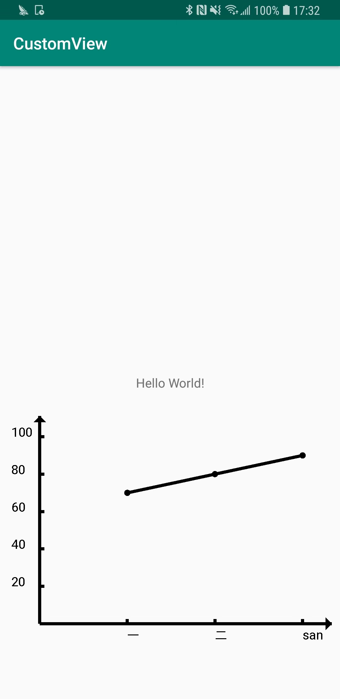
最后实现效果如下图:

继承View
创建一个class MyView 继承View
目标是写一个折线图
现在res/values下面新建一个attrs.xml文件,来申明我们需要的属性。
1
2
3
4
5
6
7
8
9
10
11
|
<?xml version="1.0" encoding="utf-8"?>
<resources>

    <declare-styleable name="LineView">
        <attr name="axieColor" format="color"/>
        <attr name="pointRadius" format="dimension" />

    </declare-styleable>

</resources>
|
先新建一个clas 继承View, 并初始化几个构造函数
1
2
3
4
5
6
7
8
9
10
11
12
13
14
15
16
17
18
19
20
21
22
23
24
25
26
27
28
29
30
31
32
|
public class MyView extends View {
    // 代码生成时,才会调用该构造函数
     public MyView(Context context) {
        super(context);
        this.context = context;
    }

    public MyView(Context context, AttributeSet attrs) {
        this(context, attrs, 0);
    }
    // xml配置时,会调用这个生命周期
    public MyView(Context context, AttributeSet attrs, int defStyleAttr) {
        super(context, attrs, defStyleAttr);
        this.context = context;
        initData(attrs);
    }

    // 做初始化配置 获取各种颜色、尺寸,还有自定义的一些属性。
    private void initData(AttributeSet attrs) {
         Log.d(TAG, "initData: ");
        // 获取xml中配置的数据
        TypedArray array = context.obtainStyledAttributes(attrs, R.styleable.MyView);
        paintColor = array.getColor(R.styleable.MyView_axieColor, context.getResources().getColor(R.color.black));

        // 画笔初始化
        paint = new Paint();
        paint.setColor(context.getResources().getColor(R.color.black));
        paint.setTextSize(40);
        paint.setStrokeWidth(10); // 线条粗细
    }
}
|
在onMeasure函数中对尺寸做约束
1
2
3
4
5
6
7
8
9
10
11
12
13
14
15
16
17
18
19
20
21
22
23
24
25
26
27
28
29
30
31
32
33
34
35
36
37
38
39
40
41
42
43
44
45
46
47
48
49
|
@Override
protected void onMeasure(int widthMeasureSpec, int heightMeasureSpec) {
    super.onMeasure(widthMeasureSpec, heightMeasureSpec);
    Log.d(TAG, "onMeasure: ");
    int height = measuretDimension(defaultHeight, heightMeasureSpec);
    int width = measuretDimension(0, widthMeasureSpec);
    top = 0;
    left = 0;
    bottom = top + height;
    right = left + width;
    setMeasuredDimension(width, height);

}

/**
 * 测量实际尺寸
 * @param defaultSize: 默认尺寸
 * @param measureSpec: 测量规格
 * @return
 */
public int measureDimension(int defaultSize, int measureSpec) {
    int resultSize = defaultSize;
    int specMode = MeasureSpec.getMode(measureSpec);
    int specSize = MeasureSpec.getSize(measureSpec);
    switch (specMode) {
        // 没有做限制,取默认值
        case MeasureSpec.UNSPECIFIED:
            resultSize = defaultSize;
            break;

            // WRAP
        case MeasureSpec.AT_MOST:
            // 要取默认值和测量值中较小值
            // 当默认值为0时,取最大值, 即宽充满屏幕
            resultSize = defaultSize == 0 ?specSize : Math.min(defaultSize, specSize);
            break;

            // 具体值 或 MATCH
        case MeasureSpec.EXACTLY:
            resultSize = specSize;
            break;

            default:
                break;
    }
    return resultSize;
}
|
先绘制两个轴线
注意canvas.draw..()方法,中的位置参数都是相对定位尺寸,都是相对于该视图左上角的坐标定位,而onLayout中的四个位置参数都是相对于屏幕左上角。
这两个里的坐标不要弄混。
1
2
3
4
5
6
7
8
| /** 绘制两条轴线 */
private void drawXY(Canvas canvas) {
Log.d(TAG, "drawXY: ");
// 绘制x轴
canvas.drawLine(left + 20, bottom, right, bottom, paint);
// 绘制y轴
canvas.drawLine(left + 20, top, left + 20, bottom, paint);
}
|
在MainActivity中配置该视图
1
2
3
4
5
6
7
8
9
| <com.justin.customview.MyView
android:layout_width="match_parent"
android:layout_height="100dp"
app:layout_constraintTop_toBottomOf="@+id/text_hello"
android:layout_marginTop="20dp"
android:padding="10dp"
app:axieColor="@color/black"
android:id="@+id/myView"
/>
|
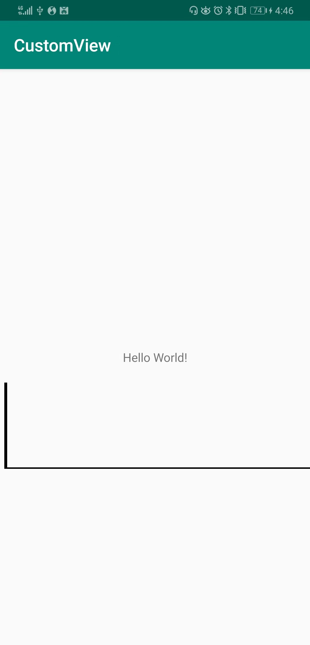
我们直接运行,效果如下:

x,y轴就画好了。但很明显我们设置的padding没起作用,因为padding是需要我们自己处理的。
新增一个方法初始化这些尺寸数据
1
2
3
4
5
6
7
8
9
10
11
12
13
14
15
16
17
18
19
20
21
| /**
* 尺寸数据初始化
*/
private void initSize () {
// 获取padding尺寸
paddingLeft = getPaddingLeft();
paddingTop = getPaddingTop();
paddingRight = getPaddingRight();
paddingBottom = getPaddingBottom();
StringBuilder sb = new StringBuilder();
sb.append("paddingLeft =").append(paddingLeft)
.append("paddingTop =").append(paddingTop)
.append("paddingRight =").append(paddingRight)
.append("paddingBottom =").append(paddingBottom);
Log.d(TAG, "initSize: ".concat(sb.toString()));
top = paddingTop;
left = paddingLeft;
bottom = height - top - paddingBottom;
right = width - left;
setMeasuredDimension(width, height);
}
|
这样我们就对padding做了处理,接下来接着绘制我们需要的图形。
我们之前绘制了两个轴,xy,但我们平常绘制的轴都会有箭头,我们再在x轴右侧、y轴上侧绘制两个箭头
1
2
3
4
5
6
7
8
9
10
11
12
13
14
15
16
17
18
|
private void drawArrow(Canvas canvas) {
    Path path = new Path();
    // 先绘制x轴三角
    //先移动到三角形一个点
    path.moveTo(right-20, bottom + 20);
    path.lineTo(right-20, bottom - 20); // 画线
    path.lineTo(right, bottom); // 画线
    path.close(); // 图形闭合
    canvas.drawPath(path, paint);

    // 绘制y轴三角
    path.moveTo(left - 20, top + 20);
    path.lineTo(left + 20, top + 20);
    path.lineTo(left, top);
    path.close();
    canvas.drawPath(path, paint);
}
|
这里主要用到了drawPath函数。其实canvas对象还有很多其他的绘制图形的方法。
设置数据并绘制点
我们已经完成了绘制两条轴线,现在要开始绘制数据了。
首先我们要确认标准线,x轴的标准线肯定就是xValue的值,
但y轴的标准线是不定的,我们要先找出最大值,确定几条标准线,确定每条标准线的值。
我们先假设我们的值在0-100以内,取5条标准线,每条间距20.
先设置两个数据
1
2
3
4
5
6
7
8
9
10
11
12
13
14
15
16
17
| // 数据
private float[] yValue;
private String[] xValue;
private int lineNum = 5;
/** 设置数据并刷新 */
public void setData(float[]yValue, String[]xValue) {
this.yValue = yValue;
this.xValue = xValue;
postInvalidate();
}
/** 设置标准线数目 */
public void setData(int lineNum) {
this.lineNum = lineNum;
postInvalidate();
}
|
然后我们开始绘制标准线、各个点
1
2
3
4
5
6
7
8
9
10
11
12
13
14
15
16
17
18
19
20
21
| /** 绘制各个点 */
private void drawPoint(Canvas canvas) {
if(xValue == null || yValue == null) return;
// 先绘制5条y轴标准线位置 取高度的90%作为图线的最高。
float maxHeight = (float)((bottom - top) * 0.9);
float itemHeight = maxHeight / 5;
for(int i = 1; i <=5; i ++) {
canvas.drawLine(left, bottom - itemHeight * i, left + 15, bottom - itemHeight * i, paint);
}
// 再绘制x轴的数据, x轴线的标准值就是x轴的值,数目也是xValue的值
float maxWidth = (float)((right - left) * 0.9);
float itemWidth = ((float) (maxWidth * 1.0)) / xValue.length;
for (int i = 1; i <= xValue.length; i ++) {
float x = left + itemWidth * i;
// 绘制轴线
canvas.drawLine(x, bottom, x, bottom - 15, paint);
// 绘制点
float y = bottom - maxHeight * yValue[i-1] / yMax;
canvas.drawCircle(x, y, 5, paint);
}
}
|
而在MainActivity.kt中,我们可以这样使用
1
2
3
4
5
6
7
8
9
10
11
| // kotlin语法
class MainActivity : AppCompatActivity() {
override fun onCreate(savedInstanceState: Bundle?) {
super.onCreate(savedInstanceState)
setContentView(R.layout.activity_main)
var xValue = arrayOf("一", "二", "san")
var yValue = floatArrayOf(70f, 80f, 90f);
myView.setData(yValue, xValue);
}
}
|
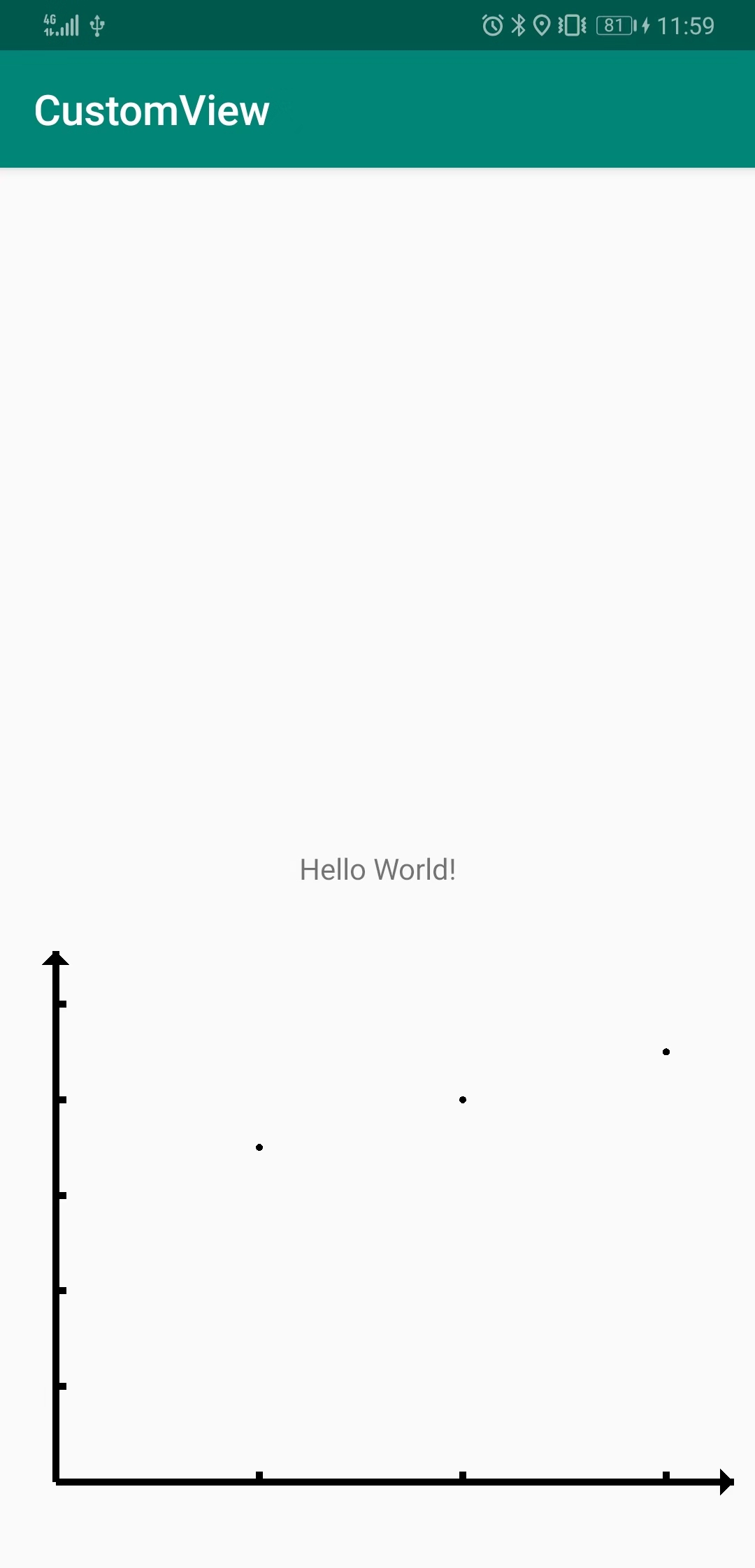
此时的实现效果:

现在我们完成了图形的大致绘制,但在x、y轴却没有一些文字说明,接下来我们就要加上这些
绘制x、y轴标准线值,将各个点连接起来。
1
2
3
4
5
6
7
8
9
10
11
12
13
14
15
16
17
18
19
20
21
22
23
24
25
26
27
28
29
30
31
32
33
34
35
36
| /** 绘制各个点 */
private void drawPoint(Canvas canvas) {
if(xValue == null || yValue == null) return;
// 先绘制5条y轴标准线位置 取高度的90%作为图线的最高。
float maxHeight = (float)((bottom - top) * 0.9);
float itemHeight = maxHeight / 5;
int itemValue = yMax / 5;
for(int i = 1; i <=5; i ++) {
canvas.drawLine(left, bottom - itemHeight * i, left + 15, bottom - itemHeight * i, paint);
// 绘制y轴标准值
canvas.drawText(itemValue * i + "", left - 90, bottom - itemHeight * i, paint);
}
// 再绘制x轴的数据, x轴线的标准值就是x轴的值,数目也是xValue的值
float maxWidth = (float)((right - left) * 0.9);
float itemWidth = ((float) (maxWidth * 1.0)) / xValue.length;
for (int i = 1; i <= xValue.length; i ++) {
float x = left + itemWidth * i;
// 绘制轴线
canvas.drawLine(x, bottom, x, bottom - 15, paint);
// 绘制点
float y = bottom - maxHeight * yValue[i-1] / yMax;
canvas.drawCircle(x, y, 10, paint);
// 绘制点与点之间的连线
if(lastX > 0f) {
canvas.drawLine(lastX, lastY, x, y, paint);
}
// 绘制x轴标准值
canvas.drawText(xValue[i-1], x, bottom + 50, paint);
lastX = x;
lastY = y;
}
}
|
最后实现效果如下图:


